Fundamentals: Terminations in Initiation Device Circuit (IDC) AKA Conventional Fire
Fundamentals in wiring are the same for all aspects of a fire alarm system. This article applies the fundamentals of initiation device circuit (IDC) termination or more commonly referred to as conventional. Typical conventional initiation circuits include some 2-wire and all 4-wire smoke detectors, passive heat detectors, water flow sensors, valve position sensors, kitchen fire suppression systems, and some pull stations.
Conventional fire initiation circuits can contain one device or a series of devices. Each circuit is called a zone or point. The fire panel cannot determine which device initiated the fire alarm; it just knows that a zone has a fire or supervisory event because at least one device on that circuit has shorted the circuit.
The wiring and termination of conventional initiation circuits are virtually identical to NAC circuits.
All conventional initiation circuits are wired the same. The grounds are common, and each positive wire goes to its own termination point. When a fire event triggers the device, the device creates almost a dead short in the circuit, which triggers an alarm condition in the Fire Panel.
To monitor the integrity of the circuit, a resistor is installed at the end of the circuit. This resistor creates a voltage drop which is measured by the panel. If a device is removed, the circuit is broken, and the Fire Alarm Panel creates a trouble condition. If a wire is cut or comes loose from a terminal, the circuit is broken and a trouble condition is created. All the wiring fundamentals presented here are required to assure the initiation circuit operates properly and alerts the user in the event of a wiring fault.
The image below illustrates the correct wire connection on a conventional initiation device. When the device is installed it will complete the connection between the two + connections. When the device is removed, the circuit is broken.
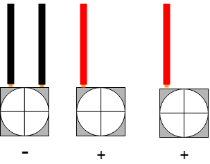
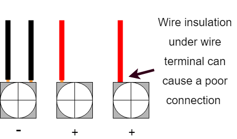
Notice the slight visibility of the copper wire. When the insulation of the wire is placed under the terminal wire clamp, it can lead to a very poor or no connection. Locating these wiring faults can be VERY VERY difficult. Always make sure you can see a little copper.
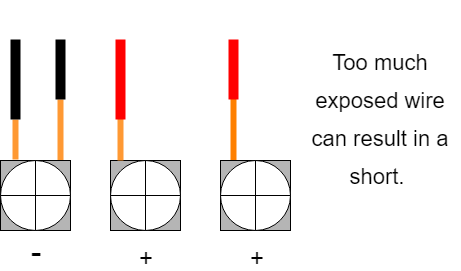
This is not correct. The bare wire should not be able to reach ANY other wire or terminal.
The image below shows the last device and the End Of Line Resistor, commonly referred to as EOL. The resistor is parallel to the device connections and so long as the device is installed the circuit is complete.
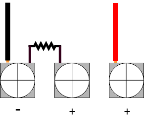
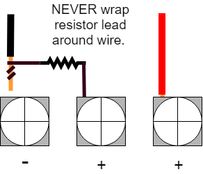
It is not always easy to secure the resistor lead under the same terminal as the larger diameter wire. It is generally incorrect to install two different gauge wires under the same terminal. To help keep the resistor secure, it is acceptable to place the resistor lead under the larger wire. Fold the end of the resistor lead over (about 1/4 inch) and slide the resistor under the larger copper wire. Tighten the terminal and give the resistor a tug to verify it is secure. IT IS CRITICAL the resistor is firmly secure.
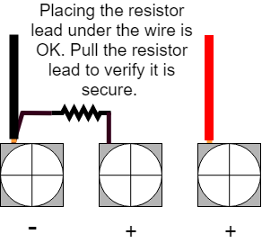
While it is tempting to wrap the resistor lead around the wire, DO NOT. Remember that the fire alarm panel must be able to monitor that every device is connected to the circuit. If you wrap the resistor around the wire and that wire becomes disconnected from the terminal, the circuit is not broken.
NEVER USE YOUR DRILL TO TIGHTEN TERMINAL CONNECTIONS. Doing so can and does strip the termination screws very quickly.