Fundamentals: Terminations in Signal Line Circuit (SLC) AKA Addressable Circuits
Fundamentals in wiring are the same for all aspects of a fire alarm system. This article applies the fundamentals of addressable initiation circuit termination, or SLC for Signal Line Circuits. Addressable Initiation circuits include smoke detectors, heat detectors, pull stations, and input modules that connect to conventional devices such as water flow sensors, and valve tamper sensors.
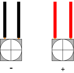
An addressable fire circuit enables a user to know exactly which device has triggered a fire alarm or supervisory event. An addressable circuit has two wires, a positive and a negative. Both negative wires go under the same terminal and unlike conventional circuits, both positive wires also go under the same terminal.
 Notice the slight amount of visible copper wire.
Each device on an addressable circuit is configured with a unique address. This is usually done by setting two dials or setting dip switches to "ADDRESS" the device. Your supervisor will show you how to address the specific device you are installing. The fire panel communicates to each device on the circuit every few seconds. If a device fails to reply, the fire panel goes into trouble due to a missing device. If you configure two or more devices to the same address, a "Duplicate Address" trouble occurs. Addressable circuits do not use resistors to monitor the integrity of the circuit. The fire panel verifies the existence and status of every addressable device every few seconds, there is no requirement to monitor the integrity of the addressable circuit, it is inherently supervised by the ability of the panel to "talk to" each device on the circuit.
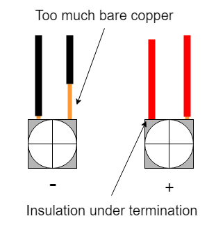
You should follow all the standard termination fundamentals. Don't place the wire insulation under the terminal or leave too much bare wire exposed.

NEVER USE YOUR DRILL TO TIGHTEN TERMINAL CONNECTIONS. Doing so can and does strip the termination screws very quickly.